Guide to Polar Alignment of a Meade LX200GPS Telescope
by Dale A. Chamberlain
April 18, 2006
Contents:
After making an investment in a telescope such as the Meade LX200GPS, you expect to be able to have the scope find an object easily and accurately, and to be able to move synchronously with the object you are observing. For this to happen, the telescope must be properly aligned. There are two types of alignment: Alt-Azimuth and Polar. If you plan on taking long exposure photos of deep sky objects, you will definitely want to operate your telescope in “Polar” mode. Alt-Azimuth is fine for general eyepiece observing or short exposure photos of the moon, sun and planets. For the purposes of this guide, we will limit the discussion to Polar Alignment.
Since our early learning, we know that the Earth spins on its axis approximately one rotation every 24 hours. It is this rotation that gives the stars in the night sky the appearance of “moving”. Just like the Sun rises in the east, so do other objects in the night sky. If you were standing facing north, east would be to your right. So the stars would appear to rise to your right, or right ascension, otherwise referred to as R.A. Keep this in mind, because you want the scope to move as close to the Earth’s movement as much as possible.
If you are in the Northern Hemisphere, you are fortunate to be living at a time when it is fairly easy to locate the celestial pole. If you drew a line that passes through the Earth’s north and south poles, and extended that line into space, the star that is closest to lining up with that line is Polaris (the North Star) in the Northern Hemisphere. This is the tail star of the constellation Ursa Minor (otherwise known as “The Little Bear” or “The Little Dipper”). (Refer to Illustration 1).

Illustration 1. Earth and alignment of Polaris
When you observe an object in the sky, the angle of that object relative to you and the horizon is the angle of declination. If you were standing precisely at the North Pole, and you were looking straight up, you would see Polaris. The North Celestial Pole (NCP) is always in alignment with the North Pole, which is 90° declination. Polaris is actually less than a degree off from the NCP, but that is close enough for what we need to do for polar alignment. But if you were in St. Louis, Missouri, you would see Polaris by looking northward at an angle of about 39°. This angle is also known as latitude. Wherever you are in the Northern Hemisphere, the angle of declination at which you would see Polaris is also your latitude.
Now what does all this have to do with the need to polar align a telescope? The telescope needs to be in alignment to the North Celestial Pole, just as if it were at the North Pole pointing straight up. That way the scope can move in much the same fashion as the earth does, thus keeping it in alignment to an object as the earth rotates. This is essential if you plan to take long exposure photography. For casual eyepiece viewing you really don’t need to polar align your scope. Alt-Azimuth mounting is sufficient since your eye will not notice the slight deviations in tracking of an object. But film, CCD or digital photography at longer exposure times will show these deviations as blurred images or streaks.
An essential ingredient in polar alignment is a mounting wedge (See Illustration 2). The wedge is mounted to the tripod where the scope is normally attached. Then the scope is mounted to the wedge. The angle of the wedge should be the same as the latitude of the observing location (for example, if observing in St. Louis, the angle of the wedge is 39°). The wedge compensates for where you are on Earth so that the scope would be pointing the same way as if it were pointing straight up at the North Pole.
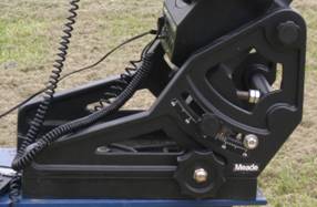
Illustration 2 - The Meade Superwedge
Top
First, level the fork arms (Illustration 3), then level the optical tube assembly (OTA) with the cap mounted and the OTA pointing straight up (Illustration 4). Set the declination circle to the latitude of the observing location (Illustration 5).
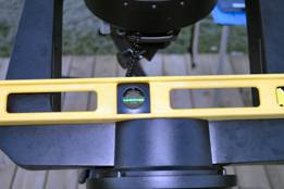
Illustration 3 - Leveling the fork arms
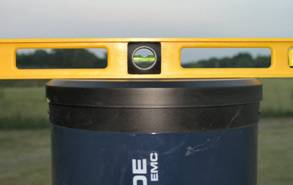
Illustration 4 - Leveling the OTA
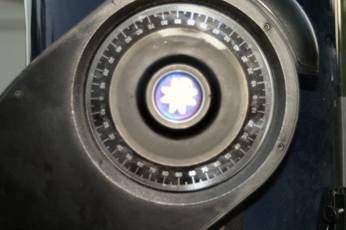
Illustration 5 - Setting the declination circle to observer's latitude
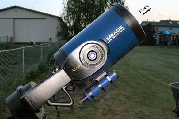
Illustration 6 - Polar Home Position
Put the scope in polar home position, with the handles and finderscope pointed downward toward the ground as in Illustration 6. Make certain the declination circle reads 90° (Remember that 90° declination is the location of the North Celestial Pole?).
Turn on the scope, and follow the Autostar instructions. The first thing you should do is check to make sure that Autostar performs a GPS fix after initialization, and that Autostar knows you are operating in “Polar Mode”. At this point it is absolutely vital that your telescope be set to Polar Mode, otherwise nothing will work correctly from here on. The reason why is because the telescope has a motor which drive the gears that moves the telescope in R.A. (right ascension) and another motor and gears that move the telescope in DEC (declination). The wedge is basically positioning the telescope as if it where at the North Pole, so when it is “tracking” an object it does not need to continuously move the scope in DEC. The only movement the telescope needs to track is R.A. Therefore, the Polar Mode setting will turn off the DEC motor and gear drive, and leave the R.A. motor and gear drive on.
When it asks for the scope to be placed in polar home position, hit ENTER. The scope will rotate on R.A. until the finderscope is in a more convenient viewing location.
Follow the instructions given by the Autostar software. When Autostar tells you to make adjustments to the scope's mount, use the knobs on the wedge to move the scope until Polaris is nearly centered in the eyepiece. Now you have completed the initial polar alignment. But further adjustments need to be made for precise polar alignment. This is accomplished through drift alignment.
To perform the drift alignment procedure, you need to choose two reasonably bright stars, approximately 3 to 5 magnitude. One star should be near the eastern horizon and one due south near the meridian. Both stars should be near the celestial equator (i.e., 0° declination). You will monitor the drift of each star one at a time and in declination only. While monitoring a star on the meridian, any misalignment in the east-west direction is revealed. While monitoring a star near the east horizon, any misalignment in the north-south direction is revealed.
First, choose your star near where the celestial equator (i.e. at or about 0º in declination) and the meridian meet. The star should be approximately 1/2 hour of right ascension from the meridian and within 5 degrees in declination of the celestial equator. Center the star in the field of your telescope.
Aim the telescope exactly at this star using a reticle eyepiece, or using a web cam that has been modified to see fainter objects with a computer and software that simulates a reticle with crosshairs. If you do not have a reticle eyepiece use your highest power eyepiece to allow you to see which way the star drifts. For very close alignment, a Barlow lens is also recommended since it increases the magnification and reveals any drift faster. Rotate the eyepiece or web cam so that a star moves parallel to the crosshairs in DEC and R.A. when using the slow motion controls. Align it so that DEC is up and down (North / South) and R.A. is right and left (East / West).
Allow the telescope clock drive to run for a while, at least five minutes. The star will begin to drift north or south. Ignore any east/west error you see.
If the star drifts up, then the telescope is pointed too far west and you need turn the azimuth control knob on the wedge (See Illustration7) that makes the star move right in the field.
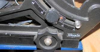
Illustration 7 – Meade Wedge Azimuth Control Knob
If the star drifts down, then the telescope is pointed too far east and you turn the azimuth control knob (Illustration 7) on the wedge that makes the star move left in the field.
After adjustment, use the slow motion controls to re-center the star. Repeat this until there is no drift for at least 5 minutes. After you have made the adjustment, if the star drifts in the opposite direction, you have overcorrected and need to turn the azimuth knob on the wedge in the opposite direction. Make small corrections. Many scopes have adjustment screws to allow this correction to be made with some precision.
Now, point the telescope at a the star near the eastern horizon and still near the celestial equator. The star should be 20 degrees above the horizon and within five degrees of the celestial equator.
If the star drifts up then the telescope is pointing too high and you will need to adjust the latitude control knob (Illustration 8) on the wedge to move the star down. If the star drifts down then the telescope is pointing too low and you will need to adjust the latitude control knob (Illustration 8) to move the star up.
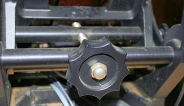
Illustration 8 – Meade Wedge Latitude Control Knob
After adjustment, use the slow motion controls to re-center the star. Repeat this until there is no drift for at least 5 minutes.
Unfortunately, the latter adjustments interact with the prior adjustments ever so slightly. So, repeat the process again to improve the accuracy, checking both axes for minimal drift. Once the drift has been eliminated, the telescope is very accurately aligned. You can now do prime focus deep-sky astrophotography for long periods.
NOTE: If the eastern horizon is blocked, you may choose a star near the western horizon, but you must reverse the polar high/low error directions. Also, if using this method in the southern hemisphere, the direction of drift is reversed for both R.A. and DEC.
4 Other Factors Affecting Guiding Accuracy
Even with a telescope with a clock drive and a nearly perfect alignment, manual guiding may still be needed to achieve pinpoint star images in photographs. Unfortunately, there are uncontrollable factors such as periodic error in the drive gears, flexure of the telescope tube and mount as the telescope changes positions in the sky, and atmospheric refraction that will slightly alter the apparent position of any object.
Even quality machined mount parts like worms, worm gears, shafts are not absolutely perfect. The parts are machined in micrometer precision at best. We require tracking precision in arc seconds for astrophotography purposes. To achieve that, the teeth on the perimeter of a gear with diameter of 8cm must be machined with accuracy of hundreds of nanometers.
As mount's shaft rotates, any error in its surface and shape and also in worm and worm gear surfaces and shapes causes a periodic bump in tracking. This is known as period error. The period of this error takes one revolution of gear (usually 5-10 minutes for most mounts).
The LX200GPS mount has the ability to suppress this error through the software of the Autostar II. It is referred to as Periodic Error Correction (PEC) and is based on recording tracking corrections made by observer by star tracking during one period. These tracking corrections are then applied during normal mount use.
The observer would make these corrections manually using the handset while the software is in the PEC recording mode (refer to the Autostar II manual for details). At the conclusion of the recording cycle, the R.A. PEC is turned on and the corrections are then applied to the periodic error.
It must be kept in mind that the other factors mentioned above, such as atmospheric refraction and telescope tube flexure will most likely have distorted the observer’s corrections during the recording cycle. There are software tools that are designed to “smooth out” these distortions to attempt to get as close to true periodic error correction as possible. An example of such a tool is PEMPro